
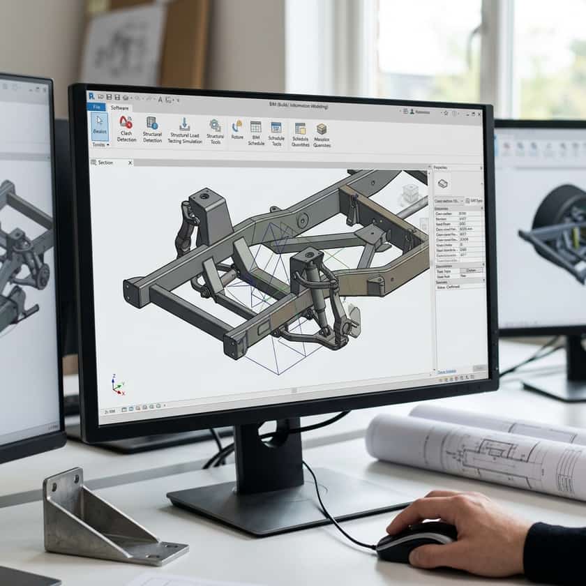
Redefining the Toolkit: Construction Software in Automotive Design
For decades, the divide between architectural design and automotive engineering seemed absolute. Architects utilized Building Information Modeling (BIM) to construct skyscrapers, while engineers used specific automotive CAD software to sculpt aerodynamic bodies. However, a growing trend among custom car builders involves repurposing powerful construction and structural design platforms for automotive projects. These sophisticated tools offer parametric modeling, clash detection, and material scheduling—features that translate surprisingly well to the complex mechanical requirements of a custom chassis or a scratch-built vehicle frame.
By applying construction software to automotive builds, makers gain access to high-end project management features often absent in simple design suites. Imagine being able to simulate the stress loads of a roll cage using the same computational analysis usually reserved for steel-frame buildings. While these tools do not replace dedicated automotive simulation software for aerodynamics, they provide a robust framework for structural integrity, interior spatial planning, and mechanical layout, proving that innovation often comes from cross-industry experimentation.
Key Advantages of Construction-Grade BIM for Auto Builds
One of the primary benefits of utilizing architecture-focused software is the ability to manage complex assemblies with precise documentation. In construction, BIM allows designers to see every bolt, beam, and conduit before physical installation. When applied to a car, this ensures that engine clearance, wiring harness routing, and fuel line placement are calculated to the millimeter. This level of foresight prevents the common 'interference' issues where components occupy the same physical space, a frequent frustration in manual automotive fabrication projects.
- Clash Detection: Identify component overlap before wasting expensive fabrication materials.
- Parametric Flexibility: Easily resize structural chassis members without redrawing the entire assembly.
- Accurate Material Scheduling: Generate detailed bills of materials for raw steel, fasteners, and interior components.
- Environmental Simulation: Model how the vehicle's interior layout handles heat dissipation and airflow.
- Visualization: Produce high-fidelity renders to test aesthetic choices before final body fabrication.
Selecting the Right Software Strategy
Choosing the right software depends heavily on your specific goals. If your objective is a clean, structural build—such as a custom tube-frame racing chassis—software designed for steel structural detailing is highly effective. These programs allow for the input of specific tubing wall thicknesses and steel grades, providing a clear map for your welder. Conversely, if your project focuses on body styling and aesthetic surfaces, you might look toward architectural tools that specialize in organic geometry and complex curves. The key is to avoid 'over-building' your digital model; keep it just detailed enough to guide your manual fabrication process without bogging down your workstation.
| Feature Type | Construction Use | Automotive Use |
|---|---|---|
| Structural Steel Analysis | Building load-bearing frames | Chassis and roll-cage rigidity |
| HVAC Simulation | Building airflow and cooling | Engine bay heat management |
| Quantity Takeoffs | Ordering lumber and concrete | Ordering sheet metal and fasteners |
| Spatial Clash Detection | Piping and wiring paths | Drivetrain and suspension clearance |
| Render Engines | Architectural previews | Car design and body styling |
Practical Implementation and Workflow Tips
To effectively use these tools, start by digitizing your critical constraints. If you are starting with a donor vehicle or a specific engine, input those dimensions first as 'fixed references.' Everything else—your custom frame, suspension mounts, and bodywork—should be built around these 'static' anchors. Always keep in mind that construction software may not natively understand automotive file formats like STEP or IGES perfectly, so you may need to export your designs into a neutral format for CNC machining or water-jet cutting services. Establish a clean naming convention early, as you will likely end up with thousands of individual components.
Finally, manage your computational resources wisely. High-fidelity rendering of a full vehicle assembly can be taxing on hardware, often taking long afternoon sessions to 'binge-render.' If your software offers cloud-based processing or simplified wireframe views, prioritize these to keep your workflow fluid. Remember that the goal is not to create a movie-quality visual, but to generate a functional blueprint. A simple, well-measured schematic is far more valuable in the workshop than an incredibly detailed model that fails when you attempt to translate it into physical steel.